Medical Pharmacology Chapter 14: Physics and Anesthesiology
Anesthetic Breathing Circuits
The anesthetic breathing circuit is designed to ensure that the patient will breathe in a satisfactory way, that is, in such a manner as to not increase breathing work or physiological dead space.
By review of definitions, the volume of gas inspired and expired with each respiratory cycle is the tidal volume which normalized per kilogram is about 6-10mls/kg.
The total volume in the respiratory cycle per minute is the minute volume and also by weight definition the functional residual capacity (FRC) is the volume of gas remaining in the lung following normal expiration.
The CO2 concentration varies through the exhalation cycle.
For example, during the first part of the expiratory cycle there is limited CO2 because the gas comes from the upper respiratory tract where limited gas exchange has occurred, corresponding to anatomical dead space which runs about 2mls/kg.
The CO2 concentration rises to about 5% corresponding to exhalation of alveolar gas.
Alveolar minute ventilation is defined by the volume of alveolar gas expired in one-minute.
Anatomical dead space would be about 25%-35% of each tidal volume; moreover, there may be regions of the lung that receive ventilation but are not perfused and as a result cannot contribute to gas exchange, corresponding to alveolar dead space.
Total dead space is the physiological dead space.
In our consideration of anesthetic ventilation systems, the term re- breathing is frequently encountered and refers to a condition in which some of the expired alveolar gas (containing 5% CO2 ) is inspired in the next tidal volume.
Some anesthetic circuits minimize this rebreathing effect since the possibility exists that significant elevation of blood CO2 .
As noted below, the particular configuration of the breathing circuit will influence the extent of rebreathing; however, several factors described the extent of rebreathing that may occur for any given anesthetic and any given circuit.29
Fresh gas flow rate
Minute ventilation
Ventilation mode, i.e. controlled or spontaneous
Tidal volume
Respiratory rate
Inspiratory to expiratory ratio
Duration of the expiratory pause
Peak inspiratory flow rate
Reservoir tube volume
Breathing bag volume
Mask ventilation
Ventilation by endotracheal tube
CO2 sampling site
Usually, fresh gas flow rates can be set high enough to minimize rebreathing in non-circle systems.
Each particular circuit design has recommended fresh gas flow rates needed to limit the extent of rebreathing.
Analogously, in circle systems, the CO2 is managed through the use of soda lime, for example, which will absorb CO2 permitting lower fresh gas flow rates.
As noted before, non- rebreathing anesthesia systems remove carbon dioxide as well as other gases, including the anesthetic gas, by atmospheric venting.
Although the systems are very advantageous with respect to stability of inspired gas concentration, other factors including economics favor relatively lower flow systems in which re- breathing occurs.
22There are a number of different circuit-types associated with non-rebreathing systems, classified both on the basis of fresh gas flow needed to prevent rebreathing as well as the how amenable the system uses in support of intermittent positive pressure ventilation. The classification is referred to as Mapleson's classification, as noted below.
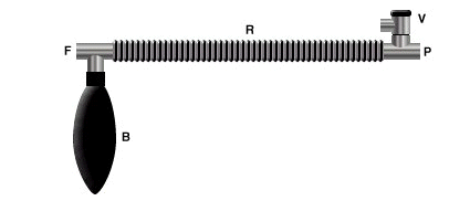
A three-way T-tube is connected to the fresh gas outlet (F), a breathing bag (B) and a
reservoir tube (R). The other end of the reservoir tube is connected to the patient (P) and a spring-loaded expiratory valve (V).
![]()
22,29 Original Mapleson type A circuit (Magill Circuit):
|
|
|

In the image below note the presence of a three-way T-tube which is connected to the fresh gas outlet (F) as well as to the breathing bag (B) and the reservoir tube (R). P refers to the patient and V to the expiratory valve (V)

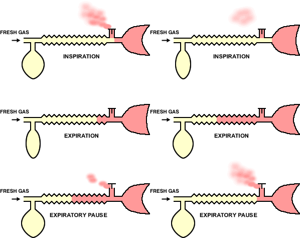
22The system functions in accord with this animation:

In the animation cycle, inspiration requires the vent-valve to close allowing fresh gas to flow to the patient from the reservoir.
During expiration, the system fills with expired gas, include the gas with positive pressure opening the valve which then allow gas escape.
During pause between expiration, fresh gas wases expired gas out of the reservoir tube minimizing rebreathing and maximizing fresh gas delivery.
30The Magill attachment (Mapleson's A) illustrates fresh gas entering the end of the system farthest removed from the patient but closest to the reservoir bag and leaving the system through the adjustable popoff valve which is located near the patient. Functionally, the system behave differently depending on whether the patient is being spontaneously ventilated or is being managed by controlled ventilation.
30Spontaneous ventilation:
During patient exhalation, dead space gas moves towards the reservoir bag while fresh gas is stored in the reservoir gas.
As exhalation continues and the pressure in the system increases, the popoff valve will be actuated inventing of the alveolar gas will occur.
If the fresh gas flow rate is high enough, dead space gas contained in the circuit volume may also be vented to the popoff valve.
With the next spontaneous respiration cycle, the patient will breathe some dead space gas still stored in the tubing, then fresh gas from the anesthesia system and from the fresh gas in the reservoir bag.
Mapleson32 and others33 determined that in order to limit or prevent rebreathing, the fresh gas flow rate should be equivalent to the alveolar ventilation or nearly so -- about 70% of minute ventilation.
Controlled ventilation:
In the case, squeezing the bag initiates popoff valve actuation and release of fresh gas.
The problem may be that, under these circumstances, inadequate removal of exhale alveolar gas results in re- breathing.
To optimize CO2 removal, appropriate conditions include a short inspiratory: expiratory ratio (I:E ratio) along with a large tidal volume with high fresh gas flow-a gas flow rate that might be 300% of minute ventilation.
With this approach CO2 removal may be optimized but at the expense of wasting anesthetic agents and placing more pressure on the waste gas scavenging system.
Some of these difficulties stimulated modification of the Magill systems as noted below (referred to as the "enclosed Magill system or Miller system"):
With the modification to fresh gas requirement is reduced since the popoff valve remains closed during the inspiratory cycle.
Modification of this type results in similar efficiency between controlled and spontaneous ventilation setups30
|
|
22Lack Circuit Co-axial modification of the Mapleson A system which facilitates expired gas scavenging
|
|
22"A four-way block is attached to the fresh gas outlet (F). This block is connected to an outer reservoir tube (R) attached to the patient (P), an inner exhaust tube (E), a breathing bag (B) and a spring-loaded expiratory valve (V). Very similar in appearance to the modified Bain, except that the inner exhaust tube has a greater diameter than the fresh gas supply tube in the modified Bain" One of the problems associated with the Magill (Mapleson A) system has to do with waste gas scavenging. The Lack circuit noted above with its repositioning of the popoff valve facilitates scavenging of expired gases. Note the animation below:
|
|
30One of the problems associated with the Magill (Mapleson A) system has to do with waste gas scavenging.
The Lack circuit noted above with its repositioning of the popoff valve facilitates scavenging of expired gases.
22"The Lack circuit is essentially similar in function to the Magill, except that the expiratory valve is located at the machine-end of the circuit, being connected to the patient adapter by the inner coaxial tube."
"Inspiration -The valve closes and the patient inspires fresh gas from the outer reservoir tube.
Expiration - The patient expires into the reservoir tube.
Toward the end of expiration, the bag fills and positive pressure opens the valve, allowing expired gas to escape via the inner exhaust tube.
Expiratory pause - Fresh gas washes the expired gas out of the reservoir tube, filling it with fresh gas for the next inspiration."
![]()
|
|
30Note in the above Mapleson B & C systems, though the fresh gas inflow port and the popoff valve are located relatively close to the patient. Furthermore there is localization volume in the circuit for collection of dead space, alveolar and fresh gas. In these systems, which are infrequently used today, free breathing is minimized with fresh gas flows about 200 % of minute ventilation.
|
|
|

![]()
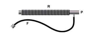
22Ayre's T-Piece
"The original Mapleson E system: A three-way T-tube whose limbs are connected to (F) the fresh gas supply from the anesthesia machine, (R) a length of corrugated reservoir tube and (P) the patient connector." See below"
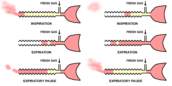
30The Mapleson E & F systems are different from those considered earlier in part because they are valveless. For the E system, which is derived from Ayre's T-piece configuration by adding tubing to the expiratory part of the circuit which effectively becomes a fresh gas reservoir during inspiration. So in sequence, during inspiration, fresh gas is stored in the expiratory part of the circuit which must have the capacity exceeding the expected tidal volume. In the exhalation phase, the exhale gas enters the expiratory part of the circuit and during the expiratory pause, this part of the circuit will be flushed with fresh gas.
|
|


22Inspiration -The patient inspires fresh gas from the reservoir tube. Expiration - The patient expires into the reservoir tube. Although fresh gas is still flowing into the system at this time, it is wasted as it is contaminated by expired gas. Expiratory pause - Fresh gas washes the expired gas out of the reservoir tube, filling it with fresh gas for the next inspiration.
![]()
|
|
|

![]()
Mapleson F system, a modification of the E systems, is also known as the Jackson-Rees system35, which consists of adding a reservoir bag to facilitate waste gas venting, a system connecting a vent valve to a scavenging subsystem. In more detail the "F" system is similar to the "E" system but in the "F" systems the exhaled and fresh gas will collect and mix in the bag. The next inspiration will result in the patient inhaling fresh gas from both the machine and from that stored in the expiratory part of the circuit. The presence of the bag allows the anesthetist to observe ventilation during spontaneous breathing as well as control ventilatory rates by squeezing the bag in the absence of spontaneous breathing. In this system, and a similar manner to that described earlier, rebreathing would be minimized by insuring adequate fresh gas flows, nominally 200%-300% of the minute ventilation rate.
30The Mapleson E & F systems are considered popular in pediatric anesthesia because of several advantages including (a) easy assembly (b) inexpensive (c) low resistance systems due to the absence of valves. On the other hand, high fresh gas flows are required as a consequence, "T"-peace systems are relatively undesirable in adults. The systems also promote reduced airway humidification.
|
|
|
Mapleson D system:
|
|
|
![]()
22,30Mapleson D - the modified Bain circuit. "A co-axial modification of the basic T-piece system, developed to facilitate scavenging of waste anesthetic gases."
|
|
|
|
|
30The Mapleson D system (above left) is characterized by a long expiratory component (corrugated tube) with a reservoir bag and popoff valve far removed from the patient.
This setup tends to being more efficient than "B" or "C" type systems.
With exhalation, fresh gas as well as alveolar and dead space gas will enter the tubing and as the pressure increases some venting will occur.
Upon initiation of the next cycle of inspiration, the patient will receive a mixture of gas with the amount of fresh gas dependent on the flow rate, duration of the patients expiratory pause and tidal volume.
With longer pauses, more fresh gas will be available; however, with shorter pauses increased CO2 rebreathing would be expected.
Similarly, if tidal volume's are large them more alveolar gas will be entering the tube which will facilitate CO2 rebreathing.
At least 200% minute ventilation fresh gas flow would probably be required to minimize or prevent rebreathing.
30In the controlled ventilation case, the above distribution of gas is comparable.
Manual reservoir bag squeezing (during inspiration) will cause popoff valve activation with release of alveolar and dead space gas and allow fresh gas to enter the patient. In the exhalation cycle, the reservoir bag will be filled first with dead space gas and fresh gas, then the popoff valve opens venting primarily alveolar gas.
As above, 200%-300% minute ventilation gas flow rates are required to prevent/minimize rebreathing. The Mapleson D is uncommonly used although when modified (coaxial modification, i.e. Bain circuit, right figure above) pediatric use is common,
Mapleson D system (coaxial modification, Bain circuit36) (above right):
This modification which represents the most commonly used variant of the Mapleson D system,allows fresh gas to enter a smaller-bore tube (7 mm internal diameter) and to flow directly to the patient.
The exhaled gas is moved through the external tube (22 mm internal diameter) to the reservoir bag and popoff valve. (the outer tube is transparent so that the inner tube can be inspected for any structural anomaly)
Bain system36,37.--The system may be used for spontaneous or assisted ventilation.
Alternatively, the reservoir bag can be detached and anesthesia ventilator hose reattached to support mechanical ventilation.
System advantages: lightweight, convenient, reusable, and easily sterilized. Since the overflow valves is located far away from the patient, expiratory gases may be readily scavenged. Also, there is some warming of the inspired fresh gases by the exhaled gas present in the outer tubing.
System disadvantages: a principal concern would be a disconnection of the inner fresh gas flows which could induce hypercarbia.
Therefore, prior to use, the Bain system must be carefully certified by the anesthesiologist.
The transparency of the outer tube is important because should the inner tube leak or if the inner tube is detached from the fresh gas port, a significant increase in system dead space could occur.
Specific procedures for leak check had been identified39.
One such method39 requires high-flow oxygen charging the circuit while including the patient end until the reservoir bag has filled.
Then, the patient end is open allowing oxygen to flush the system.
If the inner tube is structurally intact and properly align then a decrease in pressure within the circuit will be observed and the reservoir bag will deflate (Venturi effect).
If the inner tube is leaking, however, fresh gas will escape into the expiratory part of the circuit and the reservoir bag will remain inflated. Use of a main circuit requires this pre-anesthetic check
![]()
Andrews38,29 has indicated that Mapleson system performance may be best appreciated by evaluation of the expiratory component of the respiratory cycle.
|
|
In accord with this view, Andrews29, in consideration of the expiratory phase noted in the figure above, has concluded:
Mapleson A has the best efficiency of the six systems since a fresh gas inflow rate of only 1 times the minute ventilation is needed to prevent CO2 rebreathing. On the other hand, in controlled ventilation efficiency is the worst of the six given that a minute ventilation of as much as 20L may be required to prevent rebreathing.
Mapleson systems D to F are somewhat more efficient than B &C. To limit CO2 rebreathing systems D to F require a fresh gas inflow of about 2.5 times minute ventilation whereas a somewhat higher requirement needed for the B & C systems.
Considering spontaneous ventilation, the following order reflects Mapleson system efficiency with respect to limiting rebreathing A > DFE > CB. By contrast to the A, B & C the signs which are infrequently used today, the D, E, and F systems are commonly used. In the United States, the Mapleson modified D system, the Bain circuit, would be the most common.
Citations
22Anesthesia Service and Equipment, http://asevet.com/index.htm
23Goldberg, M.E., Cantillo, J, Gratz, I, Deal, E, Vekeman, D, McDougall, R, Afshar, M, Zafeiridis, A and Larijani, G. Dose of Compound A, Not Sevoflurane, Determines Changes in the Biochemical Markers of Renal Injury in Healthy Volunteers, Anesth Analg 1999; 88: 437.
24Severinghaus, JW: The rate of uptake of nitrous oxide in man. J. Clin. Invest. 33: 1183-1189, 1954
25Lowe, HJ, Ernst, EA: The Quantitative Practice of Anesthesia: Use of Close Circuit. Baltimore, Williams & Wilkins, 1981.
26Titel, JH, Lowe, HJ, Elam, JO et al: Quantitative closed-circuit halothane anesthesia. Anesth Analg 47: 560-569, 1968.
27Eger, EI II: Complexities overlooked: Things may not be what they seem. Anesth. Analg 84: 239-240, 1997.
28Weiskopf, RB, Eger, EI II: Comparing the costs of inhaled anesthetics, Anesthesiology, 79: 1413-1418, 1993
29Andrews, J.J. "Inhaled Anesthetic Delivery Systems" in Anesthesia 5th edition vol. 1 (Miller, R.D. editor; Cucchiara, R.F., Miller, Jr., E.D., Reves, J.G., Roizen, M.F. and Savarese, J.J., consulting editors) Churchill Livingstone, Philadelphia, 2000, pp 174-206.
30Eisenkraft, J.B. "Anesthesia Delivery Systems", in Principles and Practice of Anesthesiology, 2nd edition, volume 1, (Longnecker, D.E., Tinker, J.H., and Morgan Jr, G.E., Mosby, St. Louise, 1998, 1001-1063.
31Susay, SR, Smith, MA, Lockwood, GG: The saturated vapor pressure of desflurane at various temperatures. Anesth Analg 83:864-866, 1996.
32Kain, ML, Nunn JF: Fresh gas econoimics of the Magill circuit, Anesthesiology 29:964, 1968.
33Mapelson, WW: The elimination of rebreathing in various semi-closed anaesthetic systems, Br. J. Anaesth 26: 323, 1964.
34Miller, DM, Miller, JC: Enclosed afferent reservior breathing systems, Br. J. Anaesth 60: 469, 1988
35Jackson-Rees, G: Anaesthesia in the newborn, Br. Med. J. 2: 1419, 1950.
36Bain, JA, Spoerel, WE: A streamlined anaesthetic system. Can. Anaesth Soc J 19: 426, 1972.
37Milner, Q "Anaesthetic Breathing Systems", Update in Anesthesia, issue 7, article 4 (1997) http://www.nda.ox.ac.uk/wfsa/html/u07/u07_012.htm
38Sykes, MK: Rebreathing circuits: A review. Br. J. Anaesth 40: 666, 1968.
39Pethick SL: Letter to the editor. Can. Anaesth Soc J 22: 115, 1975.