|
|
|
|
|
|
|
Medical Pharmacology Chapter 14: Physics and Anesthesiology
|
|
|
|
|
|
|
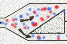
By contrast, to the "measured-flow flow devices discussed earlier, variable bypass ("Tectype") systems take the total fresh gas flow and split the flow between a bypass circuit and the vaporizer chamber.
As noted earlier, in the measured flow systems, a calculation is needed to set both the O2 flow to the vaporizing chamber as well as the total bypass flow; moreover, improper calculations in settings can lead to errors in appropriate anesthesia concentration delivery.
Figure below adapted from reference 30 and from Eisenkraft, JB: Vaporizers and vaporization of volatile anesthetics. In Eisenkraft JB, editor, Progress in Anesthesiology, vol 2, San Antonio,1988, Dannemiller Memorial Educational Foundation) (reference 40) illustrates the triangular wedge (left) we split the total gas flow into the bypass flow circuit and the circuit directed to the vaporizing chamber.
|
|
![]() The ratio of bypass flow to flow to the vaporizing chamber
is also referred to as the "splitting ratio" and its ratio will be
influenced by the choice of anesthetic agent, the temperature as well as the
vapor concentration dial setting.
The ratio of bypass flow to flow to the vaporizing chamber
is also referred to as the "splitting ratio" and its ratio will be
influenced by the choice of anesthetic agent, the temperature as well as the
vapor concentration dial setting.
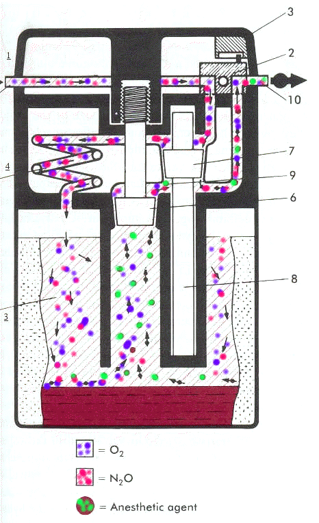
A representation of a contemporary variable-bypass, concentration-calibrated system, of the Drager Vapor 19.1 is illustrated below, adapted from Narkomed 3 anesthesia system technical service manual, Telford, PA, 1988, North American Drager and reference 30.
|
|
|
See also the animated version below:
|
|
|
|
As is clear from the diagram of above concerning the Drager Vapor 19.1 system, the output anesthetic concentration is altered by setting the concentration dial which in turn raises the controlled cone (position 6) which in turn allows saturated anesthetic vapor to contribute more significantly to the final gas mixing process.
|
|
In Figure 1 above splitting of the gas pass is represented by a triangle
30Keeping this in mind, we recall that to deliver one percent halothane (Fluothane) most of the 5000 ml/minute flow bypasses the vaporizing chamber such that about 4844 ml enters the bypass whereas about 106 ml enters the vaporizing chamber (another 50 ml is contributed by the housing vapor itself).
If we look at the ratio of gas that bypasses the vaporizer compared to the gas flow through the vaporizer we obtain the ratio of 4844 /106 (units are ml/minute); but the ratio simplifies to 46:1 and that then corresponds to the splitting ratio.
30Using another example anesthetic, enflurane (Ethrane) and a concentration-calibrated variable bypass vaporizer called an Enfluratec® (Ohmeda), we have to be able to determine the splitting ratio if we know the desired output concentration (2%, e.g.) and the total flow (1500 ml/min.).
Now if the percentage enflurane (Ethrane) is desired to be 2% and we know that the total flow is 1500 ml/minute than the volume of enflurane (Ethrane) vapor that must be added by the vaporizing chamber would correspond to 30 ml/minute (i.e. 2% x 1500 ml/minute).
If the system is set up such that 100 ml/minute carrier gas enters the vaporizing chamber, the flows divide in the following manner:
1470 ml per minute carrier gas enters the vaporizer (remember 30 ml per minute will be ultimately contributed by the enflurane (Ethrane) vapor itself), and 1370 ml/minute goes to the bypass circuit while 100 ml/minute enters the vaporizing chamber (up to now we have accounted for 1470 ml/minute) with the 30 ml/minute contributed by halothane (Fluothane) vapor.
The splitting ratio is then 1370/100 or 13.7:1. These calculations assume a temperature of 20oC.
A summary of gas flow splitting ratios for different agents is summarized below: adapted from reference 30 and Eisenkraft, JB: Anesthesia Vaporizers. In Ehrenwerth J, Eisenkraft JB, editors: Anesthesia Equipment; prinsiples and applications, St. Louis, 1992, Mosby-Year Book. (reference 43)
|
Desired anesthetic percentage |
Halothane (Fluothane) |
Enflurane (Ethrane) |
Isoflurane (Forane) |
Sevoflurane (Sevorane, Ultane) |
Methoxyflurane |
|
1% |
46:1 |
29:1 |
44:1 |
25:1 |
1.7: 1 |
|
2% |
22:1 |
14:1 |
21:1 |
12:1 |
0.36:1 |
|
3% |
14:1 |
9:1 |
14:1 |
7:1 |
maximum possible = 2.7% at 20oC. |
30One implication implicit in the about data is that concentration-calibrated vaporizers are agent specific and therefore only the particular anesthetic agent for which the vaporizer has been designing calibrated may be safely used. Clearly in order to get 1% halothane (Fluothane) vapor displaying ratio of 46:1 is required, whereas a vaporizer set up for enflurane (Ethrane) would exhibit a splitting ratio 29:1. Appreciation of the splitting ratios and their implications allows prediction of what output should be that facilitates recognition of filling errors.
30For example, if an enflurane (Ethrane) vaporizer was set to deliver 1% agent but had been inadvertently filled with halothane (Fluothane) the splitting ratio air would be 46: 29, yielding an actual halothane (Fluothane) vapor not of 1% but rather of 1.6%.
![]()
Temperature Compensation Issues:
Associated with evaporative process in the vaporizer is a decrease in temperature.
A feedback consequence of reduced temperature is a reduction in the saturated vapor pressure for anesthetics.
Accordingly, in any vaporizer system, the absence of temperature compensation will result in a reduction of anesthetics deliver to the patient.
Therefore, both measured flow systems and variable bypass systems provide for temperature compensation.
Measured flow systems such as the Copper Kettle® or VerniTrol ®, rely on the anesthesiologist reading a thermometer which reports the liquid agent temperature and requires a manual resetting of both bypass gas flows and vaporizer gas flows which will re-establish correct output for the new temperature. Such correction, although limited to the few measured flow systems which are in non-military use, provides and excellent approach to management of temperature changes.
In the more commonly used in new variable bypass systems, the temperature compensation is provided by automatic means. That is, there is a temperature-sensitive element which serves to adjust the partitioning of gas flow between the bypass and vaporizer chamber channels. The temperature compensating mechanism is typically located in the bypass gas flow component of the circuit.
A complication is that vapor pressure varies in a nonlinear way with temperature change29,31:
|
|
30The problem is that most automatic temperature compensation systems are based on linear expansion coefficients of the constituent material.
Therefore this approach can only approximate a correct temperature compensation given that the vapor pressure is not a linear function of the temperature.
Examination of the above curve indicates that for desflurane (Suprane), halothane (Fluothane), isoflurane (Forane) and sevoflurane (Sevorane, Ultane) the curve set bends upwards relatively more sharply at the higher temperatures.
It is therefore not surprising that temperature compensation systems that are linear in their mechanical properties will work better at the lower ranges of temperature.
For the Drager Vapor 19.1 system, abnormal atmospheric pressure, acceptable range is approximately + 15oC to + 35oC when acceptable means +/- 15% error in the anesthetic concentration.
At higher temperatures, the error increases as the vapor pressure vs. temperature curves deviate further from linearity, where the temperature compensation system remains linear.
30It is imperative that the boiling point for contemporary volatile anesthetic agents never be reached using current variable bypass systems since under that condition vapor output concentration will not be controlled with potentially lethal consequences.
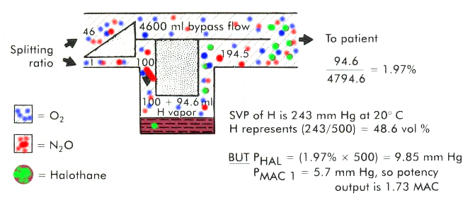
This discussion based on the contained in reference 30, references the figure below and considers the case in which a variable bypass, contemporary vaporizer is set up to deliver 1% halothane (Fluothane) which would correspond to 1.3 MAC at 760 mm Hg.
However, this set up is actually to be used at not 760 mm Hg atmospheric pressure but rather at 500 mm Hg (equivalent to about 10,000 feet above sea level). The temperature will be considered at 20oC.
Firstly, let's consider what the saturated vapor pressure of halothane (Fluothane) will now be in the vaporizing chamber.
Typically the denominator would be 760 mm Hg; however, in this case denominator is 500 mm Hg, that is 243 mm Hg/500 mm Hg (48.6 volume%), recalling that the saturated vapor pressure will be a sole function of temperature.
According to our table of splitting ratios, we would expect a ratio of 46:1 between bypass and vaporizing channel circuits.
In this example, the total gas flow to the vaporizer would be 4700 ml/min with 4600 ml/min entering the bypass circuit and 100 ml/minute directed to the vaporizing chamber.
The carrier gas represents 51.4% of the volume present in the vaporizing chamber since halothane (Fluothane) is already contributing 48.6%.
So by proportions, if 100 ml/min of carrier gas corresponds to 51.4% then halothane's contribution of 48.6% corresponds to 94.6 ml/min. (100 ml/min/51.4% = x / 48.6%)
So the actual total flow will be 4600 ml/min passing through the bypass circuit + 100 ml/min of fresh gas entering the vaporizer chamber and finally an additional 94.6 ml/min contributed by halothane (Fluothane) vapor.
Focusing on the halothane (Fluothane) vapor, 94.6 ml/min/4794.6 ml/min corresponds to about 1.97 vol% or nearly 2%-almost double what would be expected based on the dialed-in concentration (again in terms of volume%).
Extending the argument a little further, we need to consider partial pressure effects. Noting that halothane (Fluothane) in the above case is equivalent to1.97% of the gas mixture by volume, its partial pressure can be calculated by multiplying 1.97% by 500 mm Hg or 9.85 mm Hg. From our earlier discussion we recall that halothane (Fluothane) at one MAC (vol%) is equal to 0.75% x 760 mm Hg = 5.7 mm Hg which would be PMAC1. Since MAC is a measure of anesthetic potency, this hypobaric condition results in 9.85 mm Hg/5.7 mm Hg MAC or 1.73 MAC. Therefore the vaporizer dial in setting of 1% which at 760 mm Hg which correspond to 1.33 MAC, under these hypobaric conditions, 1.73 MAC was actually provided. The error corresponds to delivery of 130% of expected.
Note: from a volume% point of view there was a discrepancy of 200%; but from a potency or MAC point of view the discrepancy was only 130%.
The same formalism would apply for a measured-flow system under the same circumstances.
Figure below adapted from reference 30 and from Eisenkraft, JB: Vaporizers and vaporization of volatile anesthetics. In Eisenkraft JB, editor, Progress in Anesthesiology, vol 2, San Antonio,1988, Dannemiller Memorial Educational Foundation) (reference 40)
|
|
![]()
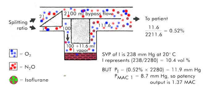
In this example, an isoflurane (Forane) vaporizer of the variable bypass design is set up to deliver 2% which corresponds to 1.74 MAC at 760 mm Hg (isoflurane (Forane) & 20oC.1 MAC = 1.15 volume%; therefore, 2% (volume%) equals 1.74 MAC recall also that 1.15 MAC represented in terms of partial pressure at 1.15 MAC = 1.15% x 760 mm Hg = 8.7 mm Hg)
We wish to compare vaporizer output and flows in the above condition, compared to the 3 atm case (3 x 760 mm Hg =2280 mm Hg), also noting that the saturated vapor pressure in the vaporizing chamber is 238 mm Hg, which corresponds to a vaporizing chamber volume% of (238mm Hg/2280 mm Hg) x 100 or 10.4 vol%.
Gas-splitting ratios are determined from lookup tables taking into account the anesthetic agent as well as the desired vol%. In this case the splitting ratio from the lookup table is 21:1 for 2% isoflurane (Forane).
Assuming the total gas flow into the vaporizers 2200 ml/minute divided as follows: 2100 ml/min entering the bypass circuit and 100 ml/min entering the vaporizing chamber.
First considering the vaporizing chamber vol% distribution: since we know that isoflurane (Forane) vapor contributes 10.4%, then fresh gas contributes 89.6%.
In terms of volumes, the isoflurane (Forane) vapor will correspond to 11.6 ml/min (100 ml/min/89.6% = x ml/min/10.4% = 11.6 ml/min)
The vaporizer total output then requires adding 2100 ml/min (bypass circuit) + 100 ml/min (vaporizing chamber) + 11.6 ml/min isoflurane (Forane) vapor. Therefore, the isoflurane (Forane) contribution is 11.6 ml/min/2211.6 ml/min or 0.52%.Remember that the vaporizer dial was sent to 2%; therefore, the actual output is considerably different 0.52 vol% compared to 2 vol% or only 26% (0.52 vol%/2 vol%).
As before, we want to compare this deviation to what is occurring with our potency measure (MAC). Remember from above that in terms of mm Hg, 1 MAC for isoflurane (Forane) = 8.7 mm Hg (PMAC1= 8.7 mm Hg).
This number is to be compared with the partial pressure of isoflurane (Forane) as it comes from the vaporizer. Since the total pressure is 2280 mm Hg (3 atm) and the isoflurane (Forane) vol%= 0.52%, then the partial pressure due to isoflurane (Forane) vapor is 11.9 mm Hg (0.52% x 2280 mm Hg).
We can now look at the MAC ratios: if 1 MAC/ 8.7 mm Hg = x MAC/11.9 mm Hg and solving for x results in x = 1.37 MAC.
In this circumstance, the desired MAC was 1.74 in accord with the vaporizer setting assuming 760 mm Hg, but the actual MAC was 1.37 given the hyperbaric state corresponding 2 3 atm.
The potency reduction was about 20%.
The schematic representation for the above case is given below. Figure below adapted from reference 30 and from Eisenkraft, JB: Vaporizers and vaporization of volatile anesthetics. In Eisenkraft JB, editor, Progress in Anesthesiology, vol 2, San Antonio,1988, Dannemiller Memorial Educational Foundation) (reference 40)
|
|
Summary concerning barometric pressure effects:
Barometric pressure changes have significant effects on vol% on volatile anesthetics; however, the magnitude of effects on the measure potency, MAC, is significantly less.
The physiological consequence is embodied entirely in MAC, therefore after computing changes in vol% it is necessary to convert the change to MAC units to appreciate the significance of the effect.
|
|
|
|
|
|
|
Citations
29Andrews, J.J. "Inhaled Anesthetic Delivery Systems" in Anesthesia 5th edition vol. 1 (Miller, R.D. editor; Cucchiara, R.F., Miller, Jr., E.D., Reves, J.G., Roizen, M.F. and Savarese, J.J., consulting editors) Churchill Livingstone, Philadelphia, 2000, pp 174-206.
30Eisenkraft, J.B. "Anesthesia Delivery Systems", in Principles and Practice of Anesthesiology, 2nd edition, volume 1, (Longnecker, D.E., Tinker, J.H., and Morgan Jr, G.E., Mosby, St. Louis, 1998, 1001-1063.
31Susay, SR, Smith, MA, Lockwood, GG: The saturated vapor pressure of desflurane at various temperatures. Anesth Analg 83:864-866, 1996.
32Kain, ML, Nunn JF: Fresh gas econoimics of the Magill circuit, Anesthesiology 29:964, 1968.
33Mapelson, WW: The elimination of rebreathing in various semi-closed anaesthetic systems, Br. J. Anaesth 26: 323, 1964.
34Miller, DM, Miller, JC: Enclosed afferent reservior breathing systems, Br. J. Anaesth 60: 469, 1988
35Jackson-Rees, G: Anaesthesia in the newborn, Br. Med. J. 2: 1419, 1950.
36Bain, JA, Spoerel, WE: A streamlined anaesthetic system. Can. Anaesth Soc J 19: 426, 1972.
37Milner, Q "Anaesthetic Breathing Systems", Update in Anesthesia, issue 7, article 4 (1997)
38Sykes, MK: Rebreathing circuits: A review. Br. J. Anaesth 40: 666, 1968.
39Pethick SL: Letter to the editor. Can. Anaesth Soc J 22: 115, 1975.
40Eisenkraft, JB: Vaporizers and vaporization of volatile anesthetics. In Eisenkraft JB, editor, Progress in Anesthesiology, vol 2, San Antonio,1988, Dannemiller Memorial Educational Foundation)
41Field Medicine, Walter Reed Army Medical Center
42Narkomed 3 anesthesia system technical service manual, Telford, PA, 1988, North American Drager
43Eisenkraft, JB: Anesthesia Vaporizers. In Ehrenwerth J, Eisenkraft JB, editors: Anesthesia Equipment; prinsiples and applications, St. Louis, 1992, Mosby-Year Book.